The core design principle of MRPS is to separate shared infrastructure from replaceable output modules in a scalable and modular manner.
- At least one high current DC supply is wired to a backplane.
- The backplane distributes the DC bus to six slots, measures aggregate current, powers local control electronics and fans.
- Each module mates with the backplane and occupies a slot. Each hosts a power-output module or accessory.
- The backplane and every carrier have their own microcontroller to manage local peripherals and a CAN-FD transceiver to communicate with the rest of the system. CAN-FD is the only inter-board communication bus.
DC input
   │
   ├── Backplane controller, current monitor, CAN-FD, and cooling
   │
   └── Shared VIN_BUS
          ├── Carrier 1 ── USB-C PD module
          ├── Carrier 2 ── Accessory or USB-C PD module
          ├── ...
          └── Carrier 6 ── USB-C PD module
This repo is going “live” with the second-generation backplane, which consolidates functions that previously lived on separate backplane and controller boards.
At least for now there is only one “supported” carrier/module but there are plans to expand the range of compatible modules in the future.
Current design targets #
To make a very long story short, the first iteration of the design is targeting a DC input of at most 30V, nominally somewhere around 24V.
This is because the current/only carrier module has a maximum input voltage of 30V.
Furthermore, the SW3538 based module can’t do more than 100 W without using non-standard configurations so the effective ‘ceiling’ here is going to be 100 W per port until a new module revision is introduced.
The only way to achieve 100W with USB-C/PD is to use 5A/20V (100W) configuration.
Just for perspective, a good quality power supply that can do ~ 27v and ~ 30A will cost somewhere in the range of 200-400 USD so there’s also a cost reason to keep things at or below the 100 W per port ceiling at this time.
Given all that:
| Property | Current target |
|---|---|
| Initial system input | Nominal 24-28 V DC |
| Module slots | Six |
| Initial USB-C policy ceiling | 20 V, 5 A, 100 W per port |
| Working aggregate input budget | Approximately 30 A |
| Cooling | Two independently switched 3-wire fans per backplane |
And so so so many additional properties that are “theoretical, untested” until I get the first physical articles in hand; they have been ordered and are expected to arrive soon.
Very early prototypes did put per-slot switching on the backplane but that was later abandoned in favor of a simpler, shared input bus design; the current design does not presently switch or limit each backplane slot.
Slot power is present whenever the shared input bus is energized due to the limited number of pins available on the connector.
For the underlying engineering record, see the repository’s system overview.
Interfaces #
System DC input #
The backplane accepts ground and VIN_RAW through a user-installed two-position
terminal. The initial population targets a nominal 24 V source. After the
aggregate current shunt, the rail becomes VIN_BUS and feeds the backplane
converters and all six slots.
External CAN-FD #
The external connection exposes ground, CAN low, and CAN high. Connector-side ESD protection and a common-mode choke protect this boundary. A normally-open 120 Ω termination option is intended only for installations where the backplane sits at a physical end of the CAN bus.
Carrier slots #
Each combined power-and-signal connector carries:
| Contact | Signal | Purpose |
|---|---|---|
| 1 | VIN_BUS | Unswitched power from the backplane |
| 2 | GND | Power and signal return |
| 3 | CANH | Shared CAN-FD high |
| 4 | CANL | Shared CAN-FD low |
Each carrier includes its own connector-side CAN protection. The backplane does not duplicate an ESD network at every slot.
Backplane-local interfaces #
- I²C connects only the backplane STM32 and aggregate INA237 current monitor.
- Two 3-wire fan headers provide ground, switched 12 V, and tachometer input.
- The external DS18B20 header provides ground, 1-Wire data, and 3.3 V.
- A Tag-Connect SWD footprint for programming and debugging the STM32.
Consult the engineering interface tables before relying on connector reference designators or fabricating hardware.
Power and cooling #
Warning
Everything below is theoretical. I have done some simulations and calculations to get a ballpark estimate but these numbers should not be taken as guaranteed performance. Once I have physical prototypes, I’ll do some tests to validate these theoretical numbers.
Initial operating budget #
| Item | Working value |
|---|---|
| Supply input | Nominal 24 V |
| USB-C output policy | Up to 20 V, 5 A, 100 W |
| Per-slot input budget | Approximately 4.7 A |
| Aggregate backplane target | Approximately 30 A |
| Aggregate current shunt | 1 mΩ |
At 30 A, the aggregate shunt develops about 30 mV and dissipates about 0.9 W. The biggest thermal issue will be the copper traces on the backplane and the general topology - all the DC is supplied from one end of the backplane so there’s a voltage drop and heating gradient along its length.
There is a simple tool to estimate voltage drop and heating along the backplane traces.
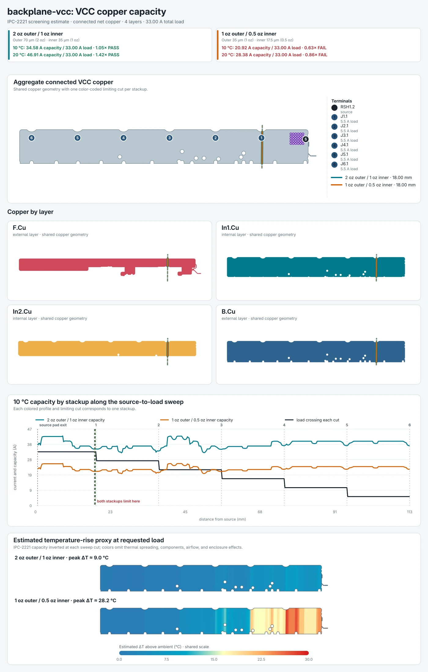
IPC-2221 screening estimate at 33 A total load, comparing 2 oz outer / 1 oz inner copper with 1 oz outer / 0.5 oz inner copper. These are calculated estimates, not measured results.
Note
The figure above is a visual representation of the estimated voltage drop and heating along the backplane traces based on the initial operating budget. It is a crude simulation and is NOT meant to be taken as precise or guaranteed.
Local rails and cooling #
The estimated 11 W loss from each fully loaded initial USB-C module makes forced-air cooling a design requirement rather than an optional feature.
To facilitate this, each backplane has a dedicated LM5164 converter for a 12V 1A rail meant to power the cooling fans. The STM32 is meant to monitor temperature from a few different locations and drive the two fans as needed.
See the engineering power budget for conductor calculations and open protection questions.