The second-generation backplane combines the controller and six-slot power distribution on one finalized PCB. Its outline, airflow cutouts, mounting features, and slot locations define the mechanical design.
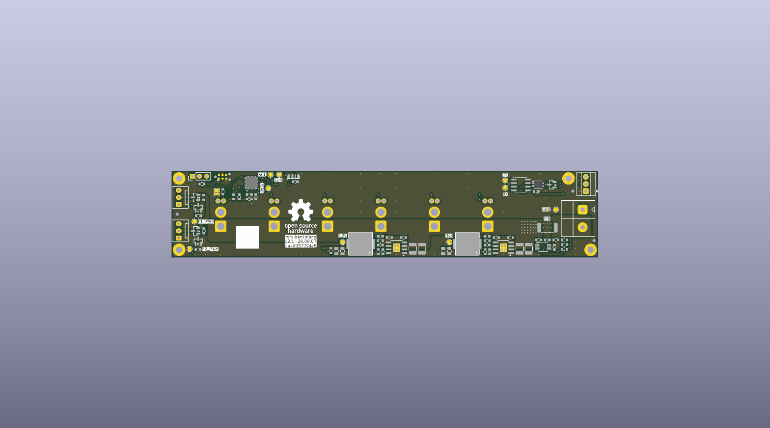
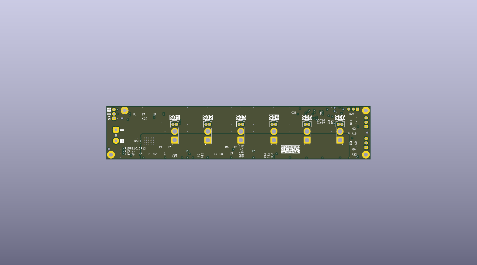
Generated from the committed PCB. Render provenance is recorded in renders.json; a preview does not establish fabrication readiness.
Responsibilities #
- Accept the raw DC input and distribute
VIN_BUSto six carrier slots. - Measure aggregate input current across a 1 mΩ high-side shunt with an INA237.
- Provide a protected external CAN-FD connection and a shared bus to all slots.
- Generate local 3.3 V for control electronics and 12 V for cooling.
- Control two independent 3-wire fan power switches and read both tachometers.
- Support an externally powered DS18B20 temperature sensor.
- Drive one local status NeoPixel.
- Expose SWD for controller programming and debug.
The backplane is designed for 24–48 V nominal input. The current SW3538 carrier limits the first population to 24 V nominal and 30 V maximum; a new carrier revision is required for 48 V operation. Do not fit current carriers to a 48 V bus. These design targets remain subject to first-article qualification.
Each carrier slot has four electrical contacts: VIN_BUS, ground, CAN high,
and CAN low. There is no backplane-to-carrier I²C bus and no per-slot logic
supply.
Status #
The finalized schematic is synchronized into a placed and routed PCB and passes ERC and PCB DRC. Current rating, thermal performance, CAN margins, fan loading, and protection behavior still require first-article validation.
Detailed implementation notes remain in the backplane README.