One carrier mates with each backplane slot and hosts one user-installed power output module. It receives unswitched DC plus CAN-FD from the backplane and generates its own 3.3 V housekeeping rail.
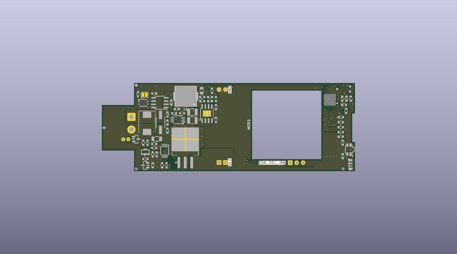
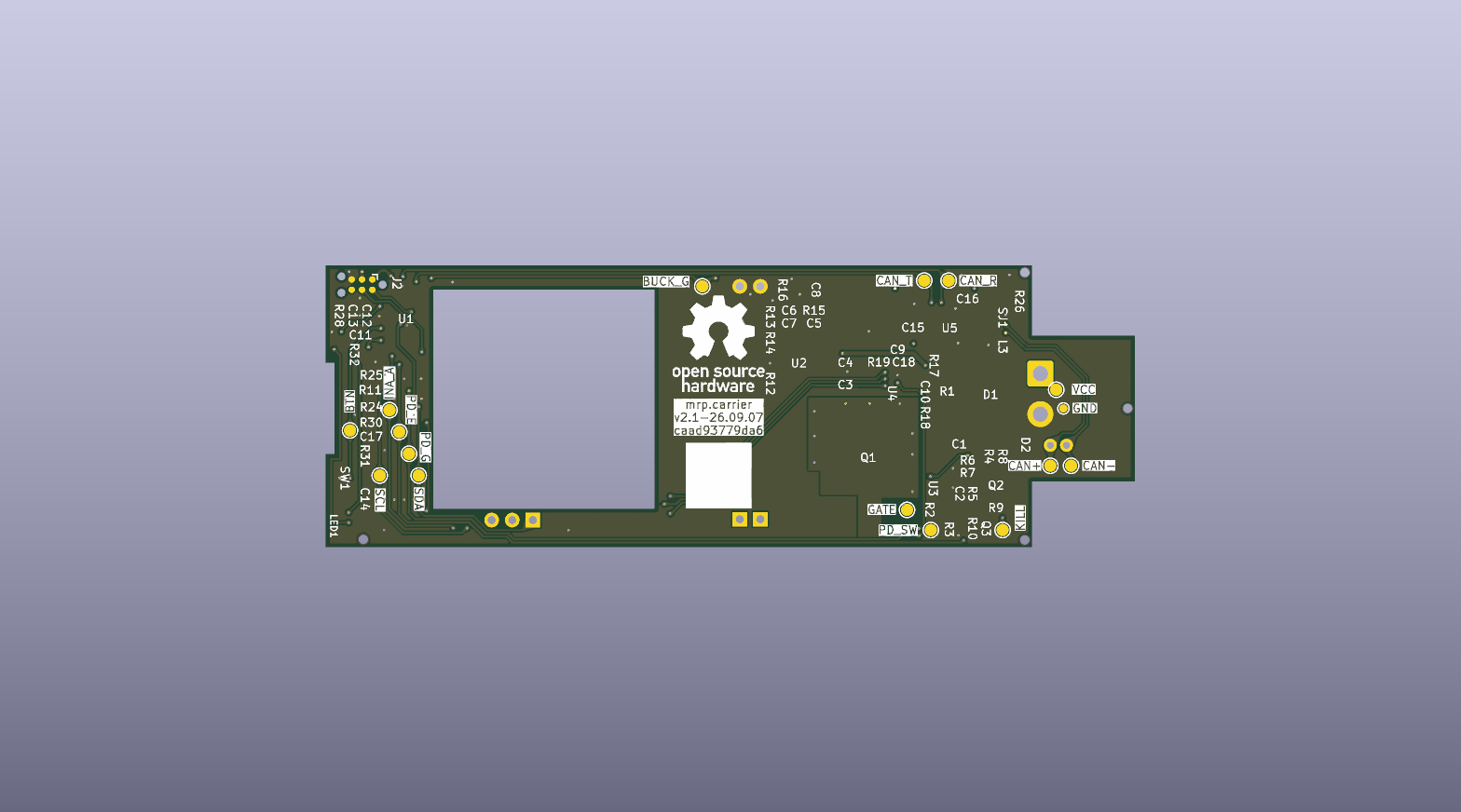
Generated from the committed PCB. Render provenance is recorded in renders.json; a preview does not establish fabrication readiness.
Responsibilities #
- Switch the high-current branch to the output module under local MCU control.
- Limit inrush and handle short-circuit, overload, undervoltage, and overvoltage conditions through dedicated hot-swap hardware.
- Measure module input voltage, current, and power with a local INA237.
- Communicate with the backplane over CAN-FD.
- Control the attached module through carrier-local I²C when required.
- Drive a local addressable status LED.
- Default the module power path off while the MCU is unpowered or resetting.
The carrier’s housekeeping electronics connect ahead of the module current shunt. Module telemetry therefore excludes the carrier controller, CAN transceiver, and status LED consumption.
The initial population is operated as a nominal 24 V, 100 W system, with a 30 V maximum carrier input. This carrier is the limiting factor in the 24–48 V nominal backplane/system architecture. A second-generation carrier with a suitably rated module and protection is required for 48 V input; the current SW3538 population must not be tested at 48 V. Future 240 W operation also requires a new end-to-end qualification.
See the detailed carrier hardware handoff for component-level design inputs and unresolved validation work.
SW3538 USB-C PD module #
The initial carrier accepts a user-installed DC-to-USB-C module based on the SW3538 controller. The module provides the USB-C connector and Power Delivery conversion while the carrier supplies protected input power and local control.
Operating policy #
Use this carrier/module population at 24 V nominal input, 30 V maximum. The backplane is designed for a 24–48 V nominal system, but its unswitched slots do not reduce voltage. A second-generation carrier with a different, suitably rated module and protection is required for 48 V operation.
The current product target stops at standard USB Power Delivery’s 20 V, 5 A, 100 W operating point. The module’s advertised 140 W behavior uses a proprietary 20 V, 7 A mode and is not part of the supported system policy.
At 100 W output, the engineering budget assumes approximately 90% conversion efficiency:
| Quantity | Budget value |
|---|---|
| Module output | 100 W |
| Estimated input | 111 W |
| Estimated input current at 24 V | 4.63 A |
| Estimated module loss | 11.1 W |
These figures are conservative planning values rather than characterization results. Cooling and full-load thermal behavior must be measured with the selected module and enclosure.
The exact module-vendor mechanical and electrical documentation is not yet in the repository. The archived SW3538 material documents the controller family, not necessarily every property of the assembled module.
See the detailed power and thermal budget for calculations and qualifications.