I thought it would be appropriate for the first entry to do two things:
- Cover the initial physical prototypes
- Announce that the first “actual” prototypes have been sent off for manufacturing.
Initial Physical Prototypes #
Please see the system overview for a high-level overview of the goal/purpose, and architecture that is being implemented in these prototypes.
Everything below is some form of initial thought/concept that led to the current design of the first physical prototypes.
From the very beginning, the target form-factor has been a 1U rack-mountable enclosure.
The very first mockups focused on the “mini-rack” form factor just to see how many distinct USB-C ports I could afford to fit within a ’narrow’ 1U space.
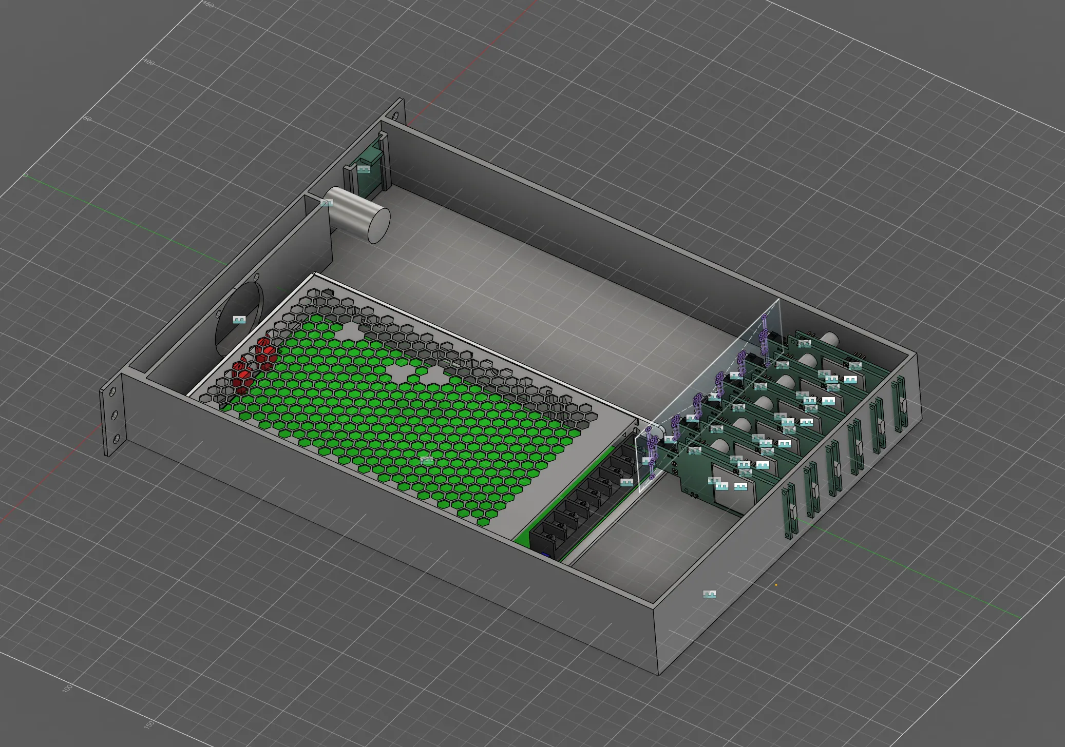
Early enclosure layout with the power supply and carrier modules.
With a standard MEAN WELL shaped power supply, it looked like the answer was “at most 6 ports”.
After some very early feedback from a small circle of friends, 6 ports is just above what they’d need for their own mini-rack home-labs in most cases. It’s enough to power up to 5 nodes + a switch… which could then use PoE to power a KVM or other peripheral devices as needed.
For the few people I spoke with that have a “tall” rack, eating another 1U for 6 more ports was considered acceptable. In 12U of height, two power units can power 10 nodes and you’d still have a bit of spare capacity for additional peripherals.
This was the beginning of a more scalable approach; you should be able to ’link’ multiple units together. Even if each unit was going to have it’s own power supply, you could still manage them collectively and link their telemetry and control interfaces for unified management across the entire rack.
Prior to this point, the plan was to do everything within a single 1U unit, likely with I2C or Modbus which does not lend itself well to scaling across multiple linked units.
I don’t have any renders to show at this point, but it just so happens that you can comfortably fit two backplanes (for a total of 12 ports) within a single “full-width” 1U unit.
Before settling on 6 total ports, some additional layouts were considered for smaller racks; this early design had some space ‘reserved’ for cable management.
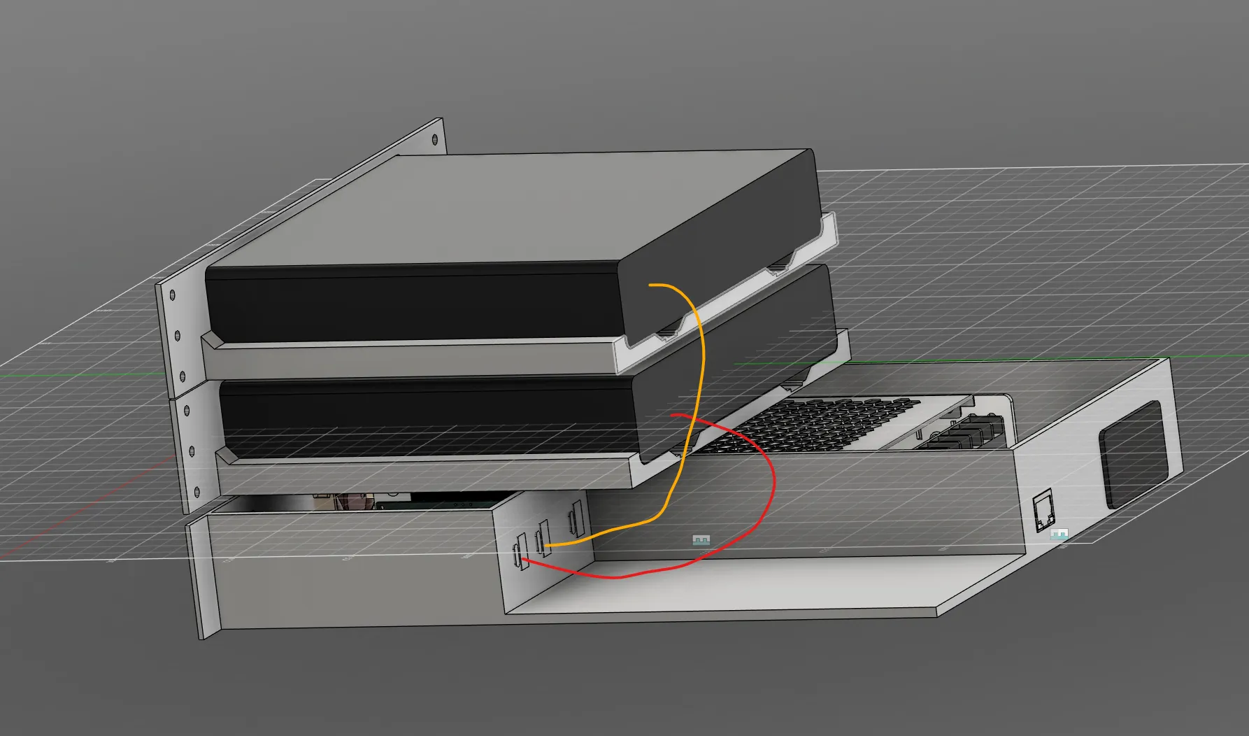
Early rack layout showing the computers above the power enclosure and proposed cable routing.
The “2-4 ports, with cable mgmt room” design was the earliest iteration of the physical layout; from the very beginning an Ethernet port for telemetry and web based management was considered essential.
I don’t have too much more from the early prototypes to show here but hopefully this gives a sense of the initial direction and design considerations and where some of the core ideas originated.
Right now, the design is focused on at most 100W per USB-C but if you look through this repo carefully, you might notice that some documents / schematic sections are “ready” for a 240W cap per port.
240W is the current limit of what USB-C can do and I’m not even sure how practical it is given that most of the loads this is aimed at need ~20V. The 240W envelope uses 5A at 48V, which would need a step-down converter to provide the ~20V required by most of the intended loads… which defeats some of the simplicity and efficiency benefits of using USB-C for these lower power devices.
So for now, 240W is a future “maybe?” goal.
Before pushing the power envelope, there are so many other aspects of this design that need proving and refinement before I add higher power capabilities and the associated complexity to the list.
Besides the “most PCs don’t operate on 48V” problem, the 100W limit is driven by several factors, some of which include:
- Going above 100W per port is going to require building my own USB-C/PD circuitry, which adds complexity and cost and is out of scope for the initial prototypes.
- There are no “off the shelf” modules that I can find on Ali Express right now that support more than 100W per port using standard USB-C/PD specifications. Some can do 140W but using non-standard implementations that would require building my own custom source/trigger circuitry.
- Thermal management becomes significantly more challenging above 100W per port, requiring more advanced cooling solutions… especially in small form-factor enclosures where airflow is limited.
- Components rated for the higher voltages/currents are more expensive.
- 100W is a lot considering this is targeting “small form-factor” PCs often used in home labs.
- Yes, lots of these PCs come with power supplies rated just above 100W but that’s typically the maximum they can draw… with the CPU pegged and several power-hungry things plugged in to the USB Ports. My intended use case assumes that the computer is not pegged at 100% load all of the time nor is it burdened with power hungry peripherals.
- In my own home-lab, 10 different general purpose compute nodes are often running simultaneously and the total power draw across all nodes is usually under 3.5A total (about 21V, so roughly 73.5W).
- At some point, I hope to be able to afford some more powerful local LLM nodes which will demand 100W+ by themselves.
PCBWay #
Shortly after this little endeavour started to move from a concept to an actual “I should actually sit down and design this properly, not hack something together” project, PCBWay reached out and offered to cover some of the costs associated with producing the first ever prototype articles.
After some consideration, I decided to take them up on their offer for a few reasons:
They’re proud to support educational and hobbyist projects like mine. That deserves recognition and appreciation!
Prototyping is expensive. SO MUCH of what makes modern day electronics ‘cheap’ is the result of large-scale manufacturing and economies of scale. When you’re producing just a few units, the cost per unit is significantly higher, and having some of those costs covered is a huge help.
Some of the BOM uses components that are new and therefore not widely available or easy to source reliably. At least one supplier went out-of-stock on a critical component while I was finishing layout! Luckily, PCBWay’s sourcing team was able to step in and secure the necessary parts for me.
- It was a huge relief to have that support, as it allowed me to focus on other aspects like firmware design/development and getting the initial version of documentation (including this post!) done instead of spending time sourcing every single component and doing a lot of logistical coordination with multiple suppliers for consignment!
So! A few days ago, I sent off the first batch of prototype PCBs to PCBWay for manufacturing and assembly.
Expect a follow up work log once they arrive and I have a chance to assemble and test the first prototypes.